The Delta Project: The Maeslant Barrier
As known, the Netherlands is mostly below sea level. Back in the day, migrants settled in the Netherlands and built their houses on high embankments near the shore. In order to protect themselves against high water, they built mounds on which they took refuge when necessary. Over time, the technique to protect our country against the sea evolved, which resulted in the creation of dams, canals, dikes, locks, and windmills. In 1953, a flood occurred that took the lives of 1,853 people and over 200,000 pieces of cattle, engulfed 200,000 hectares of fertile land, and damaged over 47,000 houses, factories, and offices. Such a disaster had to be prevented in the future, and therefore, a specially appointed Delta Committee came up with a plan. This plan resulted in the Delta Act, which was approved by parliament in 1957. In addition to providing protection against the sea, the Delta Project would improve water management, reduce soil salination, produce freshwater reservoirs, and create new recreational areas, while the new dams would greatly improve access to the southwest of the Netherlands.
The Delta Project presented Dutch hydraulic engineers with an enormous challenge. Back then, no other nation in the world had ever closed off tidal inlets of this size and depth before. Also, the know-how and technologies that were needed to do so did not yet exist. Thus, the conclusion was that these new technologies had to be developed fast. One of these innovations was prefabrication and it was soon to be widely applied. In addition, new specialist equipment was developed, including the introduction of lock caissons in 1961 and a cableway with gondolas to carry out work on wider inlets. New laboratory techniques allowed for increasingly sophisticated hydrodynamic research, computers gained ground, and measuring techniques and weather forecasts became increasingly accurate. Together, a new age had dawned for hydraulic engineering, and it looked as if the Delta Project would be completed within 20 years. The timeline in Figure 1 shows when each part of the Delta Project was completed.
 1958 - Hollandse IJssel Storm Surge Barrier
 1960 - Zandkreekdam
 1961 - Veerse Gatdam
 1965 - Grevelingendam
 1969 - Volkerak Lock
 1971 - Haringenvlietdam
 1971 - Brouwersdam
 1986 - Eastern Scheldt Dam
 1986 - Oesterdam
 1987 - Philipsdam and Krammer Lock
 1987 - The Bath Discharge Canal
 1997 - The Maeslant Barrier
 1997 - Europoort and Hartel Barrier
Figure 1: Timeline Delta Project
The original Delta Project involved sealing off as many sea inlets as possible in the southwest of the Netherlands. However, the Western Scheldt and New Waterway had to remain open to allow shipping to reach the ports of Rotterdam and Antwerp. Therefore, a major dike reinforcement along both waterways was necessary. These reinforcements required historic structures to be demolished, which led to some protests. The solution was to build a storm surge barrier in the New Waterway, for which a competition was held.
The Maeslant barrier
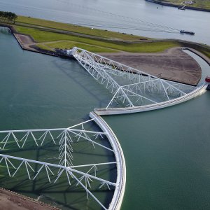
The winning design of the competition, known as the Maeslant barrier, consisted of two curved gates of 210 meters wide each (Figure 2). The construction of the project started in 1991 and was completed in 1997. When Rotterdam is threatened with water levels 3 meters above Amsterdam Ordnance Datum (AOD), also known as above mean sea level (MSL), the Maeslant barrier closes off the New Waterway 360 meters wide and 17 meters deep. The barrier has a number of highly innovative components. The gates may be the most striking, but much smaller and less visible are the special ball hinges. Both components are unique in the world. A computer system decides whether or not to close the Maeslant barrier, calculating possible water levels in Rotterdam and Dordrecht on the basis of water and weather forecasts.

Figure 2: Drawing of the Maeslant barrier
The delta
The ancient Greeks called the area around the mouth of the Nile the ‘delta’. In later years, this name was given to all river estuaries with several distributaries. The Rhine, the Meuse, and the Scheldt form the biggest delta in north-western Europe. Deltas are vulnerable to flooding, but their location, their fertile soil, and their varied fish stocks have always drawn people to them. These are very attractive places to live, and because they provide excellent opportunities for farming, fishery, trade, and industry, they are of great economic importance. This is why people throughout the ages have settled in delta areas despite the flood hazard.
The gates
Each gate consists of a steel barrier and a truss. The truss is composed of 28 hollow compartments and has a length of 245 meters. The steel barrier has an arch length of approximately 200 meters with an average height of 22 meters. The force distribution is as follows: local water pressure acts on both sides of the steel barrier, the differential pressure is transferred to the longitudinal stiffeners, and the load is then transferred to the transverse truss, followed by the so-called ‘super beam.’ Since the structure is rather slender, the stability check was of great importance. In order to cope with the complex force distribution, a finite element model was constructed of the complete structure. In addition, local models were made to describe different load-bearing behaviors in different structural elements.
Normally, the gates are kept in docks on the shores (Figure 3), but when a storm surge threatens, the docks are submerged, resulting in floating doors. Within 30 minutes, the doors are able to move to the middle of the New Waterway. Once the two gates meet, the valves in the walls open with the result that the gates sink and stop above the concrete sill on the river bed. The powerful current under the gates flushes sludge from the sill, and within an hour, the gates have landed on the clean sill, protecting the area behind from flooding.

Figure 3: The gate on shore
The ball hinge
The extreme horizontal load on the barrier during a storm equals 350 MegaNewton. The ball hinge, located at the end of the gate, must be able to rotate under these loads. In addition, the hinge must allow vertical rotation when the docks are submerged. The ball hinge is 10 meters in diameter and has a weight of 680 tonnes. Figure 4 indicates the weight of different elements within the ball hinge.

Figure 4: Weights of the ball hinge components
The load on the barrier, in combination with half of the weight of the gates, determines the size and direction of the resulting force on the ball hinge. This resulting force is transferred to the hinge foundation by cast iron bearing seats that are positioned in accordance with the direction of the resulting force. Due to frictional moments, the resulting force will not act on the midpoint of the ball, which creates a great number of different loading cases that make equilibrium with external forces. In addition, the load history is of great importance because this determines the direction and the size of the frictional moments. The ball hinge is a complex system, and therefore, only a finite element model can be used to simulate the stress distribution in the hinge.
References:
[1] Ministry of Transport, Public Works and Watermanagement and Rijkswaterstaat, 2001, The Delta Project for safety, wildlife, space, and water
[2] Berenbak J., 1991, Maeslantkering algemene inleiding – uitvloeisel van Deltawet, Bouwen met Staal 101
[3] Kerstens J.G.M, Pollemans P.J.Th. & Timmerman G.K., 1994, Maeslantkering, Nieuwe Waterweg – Gestructureerde berekeningsaanpak vormt de basis voor beheersing van het ontwerp, Bouwen met Staal 121
Figures:
1. https://www.rws.nl/water/waterbeheer/bescherming-tegen-het-water/waterkeringen/deltawerken/index.aspx
2-4. Bouwen met Staal